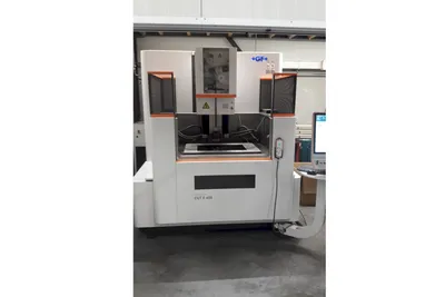
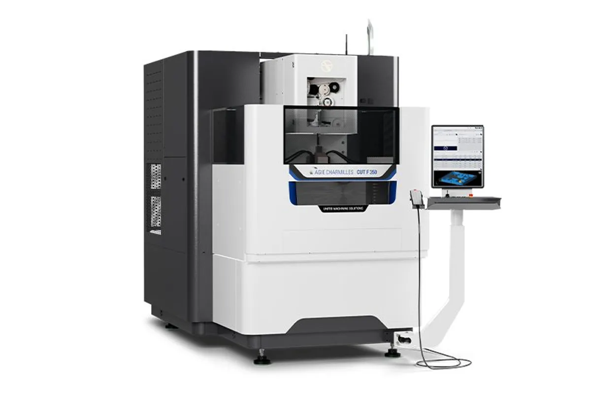
GF Machining AgieCharmilles CUT F 350
Key Specifications
X / Y / Z Travel
U / V Travel
Max Workpiece Dimensions
Max Workpiece Weight
Wire Diameter Range
Surface Finish Ra (Carbide)
Overview
The GF Machining Solutions AgieCharmilles CUT F 350 is a compact wire EDM engineered around thermal stability as its defining performance attribute. Where most wire EDMs in the 350 mm class focus primarily on cutting speed or surface finish, the CUT F 350 makes thermal management its competitive differentiator — built around the reality that dimensional accuracy in wire EDM is ultimately governed by how well the machine manages temperature.
With X/Y/Z travels of 350 x 250 x 250 mm and U/V travel of ±45 mm, the CUT F 350 targets small precision components: stamping die inserts, medical device profiles, connector tooling, watch components, and aerospace micro-features. Maximum workpiece dimensions of 820 x 680 x 250 mm with a 400 kg weight capacity provide a generous work envelope. The machine achieves surface finishes of Ra 0.14 µm on carbide and Ra 0.18 µm on steel.
The CUT F 350 features GF's Thermal Compensation System (TCS), which continuously monitors machine structure temperature and applies real-time positional corrections throughout the cutting cycle. In shop environments where temperature fluctuates 3-5 degrees C from morning to afternoon, an uncompensated wire EDM loses accuracy as its structure expands and contracts. The TCS maintains dimensional consistency across these variations.
Wire diameter support ranges from 0.10 to 0.30 mm, covering micro-detail wire through standard production wire. Taper cutting capability reaches ±30° at 50 mm height. The AC CUT control with comprehensive technology database simplifies parameter selection. The compact 1850 x 3050 mm footprint integrates easily into standard shop floor layouts.
Full Specifications
| Parameter | Value |
|---|---|
| X / Y / Z Travel | 350 x 250 x 250 mm (13.8 x 9.8 x 9.8 in) |
| U / V Travel | ±45 mm (±1.8 in) |
| Max Workpiece Dimensions | 820 x 680 x 250 mm (32.3 x 26.8 x 9.8 in) |
| Max Workpiece Weight | 400 kg (882 lb) |
| Wire Diameter Range | 0.10 - 0.30 mm |
| Surface Finish Ra (Carbide) | 0.14 µm |
| Surface Finish Ra (Steel) | 0.18 µm |
| Max Taper Angle | ±30° / 50 mm height |
| Wire Spool Capacity | 8 kg (JIS P5) or 25 kg (DIN 160) |
| Thermal Management | Thermal Compensation System (TCS) |
| Control System | AC CUT with technology database |
| Machine Footprint | 1850 x 3050 x 2450 mm |
| Dielectric | Deionized water |
| Travel X Y Z | 600 x 400 x 350 mm23.62 x 15.75 x 13.78 in |
| Min Surface Roughness Ra | Carbide: 0.14 μm / Steel: 0.18 μmCarbide: 5.50 μin / Steel: 7.09 μin |
| Dimensions Of Complete Equipment | 2160 x 3400 x 2600 mm85.04 x 133.86 x 102.36 in |
| Max Taper Angle Height | ± 30°/50 mm± 30°/1.97 in |
| Max Workpiece Dimensions | 1030 x 800 x 350 mm40.55 x 31.5 x 13.78 in |
| Max Workpiece Weight | 1000 kg2205 lbs |
| Travel U V | ± 50 mm± 1.97 in |
| Wire Diameters | 0.10-0.30 mm0.004-0.012 in |
| Max Wire Spool Weight | 8 (JIS P5), 25 (DIN 160) kg |
Specifications sourced from gfms.com — verified 2026-03-28
Strengths & Limitations
Strengths
- Thermal Compensation System (TCS) maintains dimensional accuracy across shop temperature fluctuations
- Ra 0.14 µm on carbide and Ra 0.18 µm on steel meet precision die and mold requirements
- 0.10 mm minimum wire diameter supports micro-detail cutting for fine features
- 400 kg workpiece capacity handles substantial tooling components in a compact machine
- Compact 1850 x 3050 mm footprint integrates easily into existing shop layouts
- AC CUT control with technology database reduces operator learning curve
Limitations
- ±30° taper limited to 50 mm height — less taper capability than CUT 2000/3000 series
- Surface finish (Ra 0.18 µm on steel) is good but not mirror-class like CUT S series machines
- ±45 mm U/V travel is more limited than higher-tier GF models
- Does not include the IPG generator of the CUT 2000/3000 and CUT P series
Best For
Frequently Asked Questions
01
TCS uses temperature sensors distributed across the machine structure — column, work table, and guide head assemblies — to continuously monitor thermal conditions. When the system detects expansion or contraction from ambient temperature changes, it applies calculated positional offsets to maintain programmed cutting positions. The result is consistent part dimensions from first cut through a full production day.
02
The CUT F 350 includes the Thermal Compensation System, achieves finer surface finishes (Ra 0.14 µm on carbide vs Ra 0.14 µm on the E 350), and supports 0.10 mm minimum wire diameter. The CUT E 350 is the entry-level model with more basic capabilities at a lower price point. Choose the F series when thermal stability and consistent accuracy across shifts are priorities.
03
Yes. The CUT F 350 includes automatic wire threading with re-threading and hole-threading capability, enabling confident lights-out operation on multi-feature parts. The AC CUT technology database provides reliable cutting parameters that minimize wire breaks during unattended runs.
04
Standard 0.25 mm brass wire for general-purpose cutting and 0.30 mm for maximizing speed on thicker sections. Zinc-coated wire at 0.25-0.30 mm improves speed 15-20%. For fine-detail work, 0.15 mm or 0.10 mm wire enables small internal corner radii, though cutting speed decreases proportionally.
Videos

D & R Machinery

Peak Machine Sales (Peak EDM)

Surplex

United Machining (USA)

TITANS of CNC MACHINING