Burkhardt+Weber BW300
Key Specifications
X Travel
Y Travel
Z Travel
Max Spindle
Spindle Taper
Tool Capacity
Overview
The Burkhardt+Weber BW300 is a large-format horizontal machining center from Germany's Burkhardt+Weber Maschinenfabrik GmbH, headquartered in Reutlingen, Baden-Württemberg. Burkhardt+Weber specializes in large-part horizontal machining for aerospace, defense, and heavy industry applications, competing with SNK, Mitsui Seiki, and IMSA in the heavy-duty large-travel HMC segment.
The BW300 provides an XYZ travel envelope of 3,000 x 2,000 x 2,000 mm (118 x 79 x 79 in) — positioning it in the large aerospace structural machining class for wing spars, fuselage frames, and structural titanium components that exceed the capacity of standard 1,000 mm pallet HMCs. The machine uses a fixed-table, moving-column architecture where the workpiece is fixed and the milling head moves in all axes — enabling very heavy workpiece loads without table weight limitations.
The BW300's milling head provides a 42 kW spindle at up to 4,000 RPM (optional HSK-A100 for higher speed configurations) with full 4-axis capability and optional 5-axis universal milling head for complex structural machining. The Siemens SINUMERIK 840D sl manages all axis motions including the optional continuous universal milling head.
The BW300 competes with the Fooke Endura 701L and the SNK RB-6V in the large aerospace structural machining center class. Burkhardt+Weber's differentiation is German precision engineering in the very large travel class, with aerospace process expertise for titanium and aluminum structural machining. Pricing typically runs $2.5M–$5M+ depending on configuration.
Full Specifications
| Parameter | Value |
|---|---|
| X-Axis Travel | 3,000 mm (118 in) |
| Y-Axis Travel | 2,000 mm (79 in) |
| Z-Axis Travel | 2,000 mm (79 in) |
| Table Size | Fixed floor table — workpiece mounted directly |
| Max Workpiece Weight | 30,000 kg (66,139 lb) on floor |
| Spindle Motor Power | 42 kW (56 hp) |
| Max Spindle Speed | 4,000 RPM |
| Spindle Taper | SK 50 (BT50/HSK-A100 option) |
| Spindle Torque | 2,000 Nm at low speed |
| Milling Head | 4-axis standard; 5-axis universal head optional |
| Tool Capacity | 80-station magazine ATC |
| Rapid Traverse Rate | 20 m/min X/Y/Z |
| Positioning Accuracy | ±0.005 mm (DIN ISO 230-1) |
| Repeatability | ±0.003 mm |
| Machine Weight | 120,000 kg (264,555 lb) approximate |
| CNC Control | Siemens SINUMERIK 840D sl |
| Coolant | Through-spindle coolant (TSC) 80 bar standard |
| Electrical | 400 VAC 3-phase 50 Hz, high amperage industrial supply |
Strengths & Limitations
Strengths
- 3,000 x 2,000 x 2,000 mm travel envelope accommodates the largest aerospace structural components — wing spars, fuselage sections, and space vehicle frames — in a single setup
- Fixed-table, moving-column architecture eliminates table weight limits — workpieces up to 30,000 kg can be mounted on the floor with no structural limitation from table load ratings
- 42 kW spindle with 2,000 Nm torque enables productive roughing of titanium forgings and thick aluminum billets at rates that linear-motor or smaller spindle machines cannot sustain
- Optional 5-axis universal milling head provides full 5-axis simultaneous machining capability for complex contoured aerospace structures in one setup
- German engineering heritage and Burkhardt+Weber's aerospace process expertise provide confidence in qualification for prime aerospace contractor supply chains
Limitations
- Price of $2.5M–$5M+ requires very high aerospace production volume to justify — suitable only for prime contractors and Tier 1 aerospace structural suppliers
- Machine weight of 120,000 kg requires massive reinforced concrete foundations, dedicated utility services, and crane infrastructure — facility preparation is a major capital project
- 4,000 RPM spindle is optimized for heavy structural machining — shops requiring high-speed spindle aluminum machining at 12,000+ RPM should evaluate specialized high-speed gantry machines
Best For
Frequently Asked Questions
01
In a moving-column (gantry) architecture, the workpiece is fixed to a floor-mounted table or directly to the factory floor, and the milling head moves in all three axes (X, Y, Z) relative to the stationary workpiece. This contrasts with conventional HMCs where the table moves in X and Z while the spindle moves in Y. Fixed-table architecture eliminates table size and weight limits — any workpiece that fits within the machine's travel envelope can be machined regardless of weight. The limitation is that the machine's column and beam structures must have high mass and rigidity to maintain positioning accuracy over 3,000 mm of travel.
02
A 5-axis universal milling head replaces the standard fixed-angle spindle with a tilting/rotating spindle unit that provides two additional rotary axes (typically A and C). This enables the cutting tool to approach any surface from any angle within the head's range (typically ±90 degrees in A, 360 degrees in C) without repositioning the workpiece. Universal heads for large machines use mechanical epicyclic gear drives (fork-type heads) or direct-drive motors (DD heads). For large aerospace structures with complex contoured surfaces — wing skin pockets, rib web pockets, complex fastener hole patterns on curved surfaces — the 5-axis universal head dramatically reduces the number of workpiece repositioning setups required.
03
Burkhardt+Weber machines are evaluated for aerospace applications through the prime contractor's machine qualification process, which typically includes: dimensional verification of machine accuracy using laser measurement systems per VDI 3441 or ISO 230-1; process qualification cutting tests on representative aerospace material (titanium, Inconel, aluminum); review of machine documentation including calibration records and Siemens 840D sl control verification; and an on-site demonstration of the machine's long-travel positioning accuracy. Burkhardt+Weber supports this qualification process with their application engineering team and provides the required documentation packages for AS9100 and NADCAP aerospace process qualification.
04
For titanium alloy (Ti-6Al-4V) machining on the BW300, 70–80 bar through-spindle coolant is recommended with a minimum flow rate of 15 L/min at the tool tip. High-pressure TSC is critical for titanium: it breaks the chip at the cutting zone (preventing chip re-cutting), cools the tool (extending carbide tool life), and flushes chips from deep pockets and internal passages. The BW300 is supplied with 80 bar TSC standard. For extremely demanding titanium cuts, higher pressure (up to 100 bar) can be evaluated with Burkhardt+Weber applications engineering and appropriate sealed spindle specifications.
05
A BW300 installation typically requires 4–8 weeks from machine delivery to production ready, depending on facility preparation status. The sequence is: foundation inspection and approval; machine rigging and assembly (the machine ships in sections requiring on-site assembly); electrical and coolant utility connection; geometric alignment and calibration using precision laser measurement; control tuning and spindle certification; and customer acceptance testing. Burkhardt+Weber service engineers are on-site for the full installation and commissioning period. Foundation and utility work (reinforced concrete pit, electrical, coolant drainage, compressed air) must be completed before machine delivery — Burkhardt+Weber provides foundation specification drawings at order time.
Community Discussions
Community discussion — How many W&S owners here? - Practical Machinist
Pricing and buying discussion — New Manual Lathes brands and where to buy from ...
Troubleshooting and problem-solving — Webster bennett DH type machine manuals - Practical Machinist
Community discussion — 1966 Webster & Bennett VTL oil questions - Practical Machinist
Links to community discussions. Summaries are editorial — visit the original thread for full context.
Related Machines
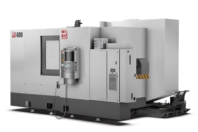
Haas EC-400
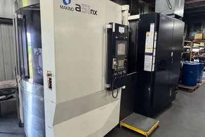
Makino a51nx
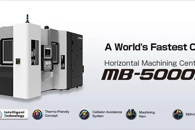
Okuma MB-5000HII
DMG Mori NHX 5000
Makino a61nx